


 Zhejiang Youji Machinery Technology Co.,Ltd >> Product >> Valve fittings >> Pneumatic Actuator >> AT
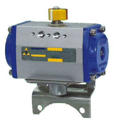
AT
Message If you want any further detail data and drawing,please contact us.
| Series : | Pneumatic Actuator |
| Name : | AT |
| Model : | AT |
| PDF-DOWNLOAD : | |
| Click : | 286 |
|
.Design Feature .
1.Unique tw0—way travel regulation.
2.Tight dual-piston gear and rack structure,with precise clutch and stable output torsion.
3.The cylinder frame is made of Crimp alufer, with hard anode oxidation treatment that the surfa-ce
texture is hard and firm.and strong wear—proof。
4.Inside the piston,have mechanical guide,O-type ring and bearin9,which avoid the nonmetal
and metal of contact that lessened wear.
5.The Connect Size is following international standard IS0521 1一DIN3337-VDl/VDE3845 NAM—
UR.which can change with mostly common pneumatic executor.
6。Dual-action and single—action(spring return)type adopted same frame and den cover.
7.All the active parts use wear-Proof material bearing.
8.air—supply hoe Confirm to NAMUR standard.Or with the transfer board confirming to the NAM—
UR standard.Matching board type magnetic valve can install directly.
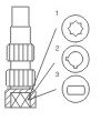
9.Unique location indicator。
10.According to requirement,can install magnetic valve,massage replier and localizer(openn—
ess indictor),triplet and manual operation structure.
II.Technology data
1.Working media。drying o r lubricating air,non-corrosive air.
2.Air source Pressure:double-action return 4~8bar.SP ring return 5~8bar
3.Temperature:一200C~+800C
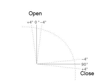
4.Outer travel regulation:90。±40
5.Inner travel regulation:90。±4。
 |
||||||||||||||||
|
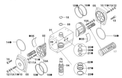
Part |
Name | Quantity | Protection | Material |
| 01 |
Main body |
1 | Alufer material | Hard anode oxidation |
| 02 | Piston | 2 | Alufer | - |
| 03 | End cover | 2 | AluferOxygen | Coating |
| 04 | Driving axes | 1 | Medium carbon steel | Coating with nickel and phosphor |
| 05 | Bearing main body | 2 | Nylon | - |
| 06 | Bearing—bushing top | 1 | Nylon | - |
| 07 | Bearing bushing bottom | 1 | Nylon | - |
| 08 | Push force carrier ring | 1 | Nylon | - |
| 09 | Plug | 2 | Acrylonitrile rubber | - |
| 10 | Outer travel screw | 2 | Stainless steel | - |
| 10A | lnner travel screw | 2 | Stainless steel | - |
| 11 | O-type ring Screw | 4 | Acryloniteile rubber | - |
| 11A | Carrier ring | 4 | Stainless steel | - |
| 12 | Nut screw | 4 | Stainless steel | - |
| 13 | End bolt | 8 | Stainless steel | - |
| 14 | O-type ring end cover | 2 | Acrylonitrile rubber | - |
| 15 | 0-type ring piston | 2 | Acrylonitrile rubber | - |
| 16 | Bearing piston | 2 | Nylon | - |
| 17 |
Loading spring |
6+6 Max.6+6 |
Spaecial steel | Special protection |
| 18 | Spring nip | 1 | Spaecial steel | - |
| 20 | O-type bearing top | 1 | Acrylonitrile rubber | - |
| 21 | O-type bearing top | 1 | Acrylonitrile rubber | - |
| 22 | O-type bearing bottom | 1 | Acrylonitrile rubber | - |
| 23 | O-type bearing bottom | 1 | Acrylonitrile rubber | - |
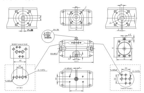
| Type | AT1 | AT2 |
AT3 |
AT4 |
AT5 |
AT6 |
AT7 |
AT8 |
AT9 |
ATl0 |
| A | 91 | 112 |
128 |
154 |
184 |
215 |
257 |
310 |
370 |
420 |
| C | 58 | 80 |
94 |
122 |
142 |
174 |
217 |
268 |
324 |
374 |
| D | 20 | 20 |
20 |
20 |
30 |
30 |
30 |
30 |
30 |
30 |
| ΦE | 12 | 18 |
25 |
25 |
30 |
45 |
50 |
65 |
75 |
90 |
| F | 51 | 51 |
80 |
80 |
130 |
130 |
130 |
130 |
130 |
130 |
| G | F03-36 | F05-50 |
F05-50 |
F07-70 |
F07-70 |
F10一102 |
|
|
|
|
| H | F05-50 | F07-70 |
F07-70 |
F10—102 |
F10—102 |
F12—125 |
F14-140 |
F16—165 |
F16—165 |
200 |
| I | M5*10 | M6*10 |
M6×10 |
M8x12 |
M8X12 |
M10×15 |
|
|
|
|
| J | M6*10 | M8*12 |
M8×12 |
M10×15 |
M10×15 |
M12x18 |
M16×20 |
M20×22 |
M20×22 |
M20×25 |
| 口K | 11*11 | 14*14 |
17×17 |
19×19 |
22×22 |
27×27 |
36×36 |
46×46 |
46X46 |
60×60 |
| L | 131 | 185 |
230 |
290 |
295 |
368 |
474 |
592 |
664 |
732 |
| L1 | - | - |
|
|
357 |
446 |
574 |
702 |
760 |
970 |
| M | 14 | 16 |
20 |
23 |
39 |
46 |
49 |
63 |
68 |
78 |
| S | 8 | 10 |
14 |
14 |
1 9 |
28 |
28 |
46 |
46 |
60 |
| P*深 | 8*12 | 10*13 |
10×15 |
14×22 |
20×24 |
28×30 |
32X34 |
40X40 |
40×40 |
50×50 |
| Q | 12 | 16 |
1 6 |
22 |
30 |
42 |
48 |
60 |
80 |
100 |
| ΦR | 12.7 | 12.7 |
15.9 |
19.1 |
22.3 |
28.6 |
31.75 |
33.5 |
41,2 |
50.7 |
| T | 14.2 | 14.2 |
14.2 |
18.4 |
21.6 |
24.8 |
32.1 |
35.3 |
37.4 |
45.3 |
| ΦT | 24 | 29 |
38 |
48 |
63 |
68 |
89 |
118 |
135 |
155 |
| Z | 3 | 3 |
5 |
5 |
5 |
8 |
8 |
10 |
12 |
12 |
| Y(深) | 32 | 32 |
32 |
45 |
45 |
45 |
45 |
50 |
65 |
70 |
| Air source nozzel | G1/8" | G1/8" |
G1/8” |
G1/4“ |
G1/4“ |
G1/4“ |
G1/4” |
G1/4“ |
G1/4” |
G1/4” |
V1.Double action output torsion table
| Type | Ai r source pressure(bar) | |||||||||
| 0.1 | 0.2 | 0.3 | 0.4 | 0.5 | 0.6 | 0.7 | 0.8 | 0.9 | 1.0 | |
| Double action output torsion(N.m) | ||||||||||
|
ATl |
3.4 |
6.8 |
10.2 |
13.6 |
17 |
20.4 |
23.8 |
27.2 |
30.6 |
34 |
|
AT2 |
8.8 |
17.5 |
26.3 |
35.1 |
43.9 |
52.6 |
61.4 |
70.2 |
79 |
87.7 |
|
AT3 |
17.3 |
34.5 |
51.7 |
69 |
86.2 |
103.5 |
120.7 |
138 |
155.2 |
172.5 |
|
AT4 |
36.1 |
72.5 |
108.3 |
144.5 |
180.5 |
216.7 |
252.7 |
288.9 |
325 |
361.1 |
|
AT5 |
69.35 |
138.7 |
208.1 |
277.4 |
346.75 |
416.1 |
485.5 |
554.8 |
624.2 |
693.5 |
|
AT6 |
114.6 |
229.2 |
343.8 |
458.4 |
573 |
687.6 |
802.2 |
916.8 |
1031.4 |
1146 |
|
AT7 |
238.7 |
277.4 |
716.1 |
954.8 |
1193.5 |
1432.2 |
1670.9 |
1909.6 |
2142 |
2387 |
|
AT8 |
503.6 |
1007.2 |
1510.8 |
2014.4 |
2518 |
3021.6 |
3525.2 |
4028.8 |
4532.4 |
5036 |
|
AT9 |
805.8 |
1611.6 |
2417.4 |
3223.2 |
4029 |
4834,8 |
5640.6 |
6446.4 |
7252.2 |
8058 |
|
ATl0 |
1279.6 |
2559.2 |
3838.8 |
5118.5 |
6398 |
7677.6 |
8957.2 |
10236.9 |
11516.4 |
12796 |
VI l.Single action output torsion table
| Type | Air source pressure(bar) | Spring torsion N.M |
||||||||||||||||
| Spring quantitty |
|
|||||||||||||||||
| Spring Reset executing structure output torsion(N.m) | ||||||||||||||||||
| 0° | 90° | 0° | 90° | 0° | 90° | 0° | 90° | 0° | 90° | 0° | 90° | 90° | 0° | |||||
|
ATlSR |
4 |
|
9.1 |
2.3 |
12.5 |
5.7 |
15.9 |
9.1 |
19.3 |
12.5 |
22.7 |
15.9 |
11.3 |
4.5 |
||||
|
AT2SR |
4 |
|
23.6 |
3.8 |
32.4 |
12.6 |
41.1 |
21.1 |
49.9 |
30.1 |
58.7 |
38.9 |
31.1 |
11.5 |
||||
|
AT3SR |
4 |
|
44.8 |
10.4 |
62 |
27.6 |
79.3 |
44.9 |
96.5 |
62.1 |
113.8 |
79.4 |
58.6 |
24.2 |
||||
|
AT4SR |
4 |
57.6 |
22.5 |
93.8 |
58.7 |
129.8 |
94.7 |
166 |
130.9 |
202 |
166.9 |
238.2 |
203.1 |
?85.8 |
50.7 |
|||
|
AT5SR |
2 |
|
|
|
206 |
69.75 |
276.1 |
139.1 |
345,5 |
208.5 |
414.8 |
277.8 |
277 |
140 |
||||
|
AT6SR |
2 |
|
|
|
326 |
115 |
440.6 |
229.6 |
555.2 |
344.2 |
669.8 |
.458.8 |
458 |
247 |
||||
|
AT7SR |
2 |
|
|
|
766.5 |
282.5 |
1005.2 |
521.2 |
1243.9 |
759.9 |
1482.6 |
998.6 |
911 |
427 |
||||
|
AT8SR |
3 |
|
|
|
1470 |
692 |
1973.6 |
1195.6 |
2477 |
1699.2 |
2980 |
2202 |
1826 |
1048 |
||||
|
AT9SR |
3 |
|
|
|
2275 |
769 |
3080 |
1574 |
3886 |
2380 |
4692 |
3186 |
3260 |
1754 |
||||
|
ATl0SR |
3 |
|
|
|
3966 |
1297 |
5245 |
2576 |
6525 |
3856 |
7804 |
5135 |
5101 |
2432 |
||||
Note:the spring quantity is the number of the cyilnder and the output torsion is the general torsion
VIII、The weight,content and openness time table of the pneumatic equipment
| Number | TA1 | TA2 | TA3 | TA4 | TA5 | TA6 | TA7 | TA8 | TA9 | TA10 | |||||||||||
| DA | SR | DA | SR | DA | DA | SR | DA | SR | DA | SR | DA | SR | DA | SR | DA | SR | DA | SR | DA | ||
| Content | 升 | 0.25 | 0.163 | 0.72 |
0.47 |
1.4 |
0.91 |
2.9 |
1.89 |
5.6 |
3.7 |
9.3 |
6.1 |
19.6 |
12.7 |
41.2 |
26.8 |
65.6 |
42.6 |
104.6 |
68 |
| Open-close time | 秒 | ≤0.5 | ≤0.83 | ≤1.0 |
≤1.6 |
≤1.5 |
≤2.5 |
≤2.0 |
≤3.2 |
≤2.0 |
≤3.1 |
≤4.0 |
≤6.2 |
≤7.O |
≤10.3 |
≤9.O |
≤13.5 |
≤10.0 |
≤14.7 |
≤1.1 |
≤16.2 |
| Weight | Kg | 1 | 1.1 | 2.1 |
2.2 |
3.75 |
3.9 |
6.1 |
6.3 |
11.1 |
13.8 |
20.3 |
24.9 |
33.7 |
52.1 |
72.3 |
90.4 |
89.6 |
110.5 |
98.7 |
125.6 |
VIIIl.How to select pneumatic equipment
|
9.1 Before install the pneumatic equipment on the valve,the followings should be noted |
|
9.1-1 The torsion force of valve +safe coefficient=the needed torsion |
| 9.1-2 Fix on the air source of valve +safe coeffcient=the needed torsion. |
|
9.2 In installation,note that: |
|
9.2-1 the valve stem and the pneumatic equipment in the same axes line. |
| 9.2-2 the connector and frame should be precisely processed by machine. |
| 9.3 lnstallation |
| 9.3-1 Confirm the operation type of the valve (nomal openness or normal closeness),install the connecto in the valve. |
| 9.3-2 Fix on the needed angle of the frame connect and install direction (in same line or intercross).The r-ecolving valve stem should in the required position. |
|
9.3-3 Forbidden discharging the pressing valve. Use suitable safe program prepare for the installation go the connection frame. |
|
9.3-4 Check the coupling and pneumatic equipment transmission axle.then point the pneumatic equipm— |
|
9.3-5 The air source nozzle AT1~AT3 is RC1/8 with transfer board.AT4~AT10 is RC1/4 and NAMUR sta— |
|
9.4 Select single action form: |
|
9.4-1 Fix on the torsion force of the valve,the lubricating liquid and adds 20%safe coefficient,the grain m- edia65%safe coefficient |
|
9.4-2 After confirming air source pressure,check the near torsion(openness)in the air source pressure d— |
|
9.4-3 Then check(90°degree)spring end torsion(closeness). |
|
9.4-4 Select the near max.size in the single action output torsion table then left along this data line to find the specification of the pneumatic equipment. |
|
9.5 Double action form selection: |
| 9.5-1 Fix on the torsion force of the valve and the pressure of the air Source.Find the near torsion data and leftward to find the specification(the retain look at the output torsion table). |
X. Air Tube principle map
(two-position five-way single conytrol valve)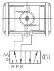 |
(two-position three-way single conytrol valve)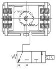 |
| Double action controller | Single action conteoller |
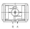
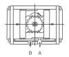
XI. Travle regulation ptinciple map
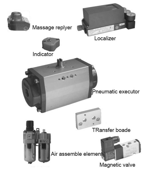
Xll.The Function and usage of accessories of pneumatic equipment
|
.Double action pneumatic executor:to control openness and closeness of the valve. |
|
.Single action pneumatic executor:to auto—close the valve when the Circuit or air line cuts off or has trouble. |
|
.Single electric controlling magnetic valve:the valve open(close)in power supply and close(open)in power |
|
.Double electric control magnetic valve:the valve opened when one of the coil electrified and close when the?other coil electrified.Has the function of memory. |
|
。Information Replyer:for far distance transmit the signal of the valve switch position· |
|
.Electric localizer:regulate and control the media flow of the valve according to the current signal(4—20mA)- |
|
.Electric changer:change the current signal into air pressure signal and used with pneumatic localizer-The |
|
.Pneumatic localizer:control and regulate the of the valve according to the p ressure signal(0·02—0.1 Mpa) |
|
.Pneumatic triplet:decompress valve,filter and oil ?filter.Has the function of stabilized the air source,Clean |
|
.Manual operating structure:to operate the openness or:closeness of the valve when the electric circuit andair circuit cut off or troubled. |
VIII、 Connection specification
| bottom | top | air source connection | transfer axle type |
 |
 |
 |
 |
| (DIN German lndustrial Standard) | Namuer-VDI VDE3845 | Namuer | ISO5211 Standard b-ureaurequired execu-tion |
VIIII.Mode workout specification
| AT | 1 | DA | S |
| 1 | 2 | 3 | 4 |
1 Executor mode
2 Cylinder body specification
3 DA:double action SR: single form
4 Output axle form
5 Manual structure
XV、Accessory sets mp
Affix1.ZVJB25 small-sized magnetic change valve
|
Feature of ZVJB25 series small—sized magnetic change valve |
|
A.Power |
|
B.The sealing parts need not oil supply and the exhausted airwould not pollute the environment. |
|
C.With auto—lock manual operation knob. |
|
D.Long service life,more than l0 million times. |
|
E.Small volume. |
|
G.With protection circuit and indicator light. |
|
H.The product has normally type and explosion—proof type. |
|
The explosion..proof type is EEXmll T4. |
Main technology parameter
| type | ZVJN25 | AVJB23 | |
| Change time(S) | 0.05 | ||
| Connecting tube worm |
P | G1/4 | |
| R1 R2 | 1/8 | ||
| Efficient section area(mm2) | 35 | ||
| Working media | Air | ||
| Oil supplyNone | oil not supply | ||
| working pressure(Mpa) | 0.15~0.9 | ||
| Check action (Mpa) | 1.4 | ||
| working temperature range °C(environmental temperature and media temperature) | (use in the condition of not freeze) | ||
| Manual operation | Manual typePress down (auto-lock) | ||
| Install type | Free | ||
| Vibration resistance/shock resistance | 5G/30G | ||
| Commend lubricating oil rated voltagRust | steamer engine oil HU-30(GB253)or equivalence | ||
| ZVJB25-1 1 1 D | |
| Tubing type | Connection type |
| Controlling type | Voltage |
| 1 | code | describe | remarks |
| 25 | two-position Five-way | ||
| 2 | 1 | tubing type | |
| 2 | boarding type | ||
| 3 | 1 | single electric type | |
| 2 | double electric type | ||
| 4 | 1 | AC220V | |
| 2 | DC24V | ||
| s | special voltage | Thespecial voltage can be made in order | |
| 5 | ZVJB connection type | ||
| R型type | Direct bushing type | ||
| D | DINbase type | ||
|
The guide valve has two connection types,type Randtype D.Type Ris the direct bushing type,has none of anycircuit equipment,easy and direct connection.Type D also |
standard specification
| type |
AC1OA |
AC20A |
AC30A |
AC40A |
AC40A-06 |
|
| forming elements | Filter compression release valve |
AW1l0 |
AW20 |
AW30 |
AW40 |
AW40-06 |
| Oil sprayer |
AL1O |
AL20 |
AL30 |
AL40 |
AL40一06 |
|
| connection caliber |
M5×0,8 |
1/8 |
1/4 |
1/4 |
3/4 |
|
| connection caliber of pressure meter |
1/16 |
1/8 |
1/8 |
1/4 |
1/4 |
|
| adopting liquid | Air | |||||
| pressure-proof testing pressure | 1.5Mpa | |||||
| the top pressure | 1.0Mpa | |||||
| setting pressure range | 0.05~0.7MPa | 0.O5~0.85MPa | ||||
| overflow pressure | setting pressure+0.05Mpa {overflow rate0.1 11/min(ANR)} | |||||
| environmental temperature and using fluid temperature |
一5—60℃(未涑结畴before freeze) | |||||
| filter precision | 5Um | |||||
| commend oil | (ISO V932)touping N0.1 0il(ISO V932) | |||||
| cup material | Merlon | |||||
| structure/filter compression release valve |
overflow type | |||||
| (Kg)quality(Kg) |
0.20 |
0.59 |
0.75 |
1.41 |
1.46 |
|
| appendix | the protect cover of cup |
|
|
● |
● |
● |
| type | connection caliber |
standard specification | optional specification | |||||||||||||||
| A | B | C | D | bracket install size | pressure meter | withauto— drainer |
||||||||||||
|
E |
F |
G |
H |
J |
K |
ΦK |
L |
M |
N |
p |
Q |
B |
||||||
| AC1OA | M5×0.8 | 56 | 108 | 48 | 50 |
28 |
25 |
20 |
27 |
7 |
4.5 |
4,5 |
2.8 |
40 |
26 |
|
- |
126 |
| AC20A | 1/8·1/4 | 83 | 160 | 73 | 80 |
41.5 |
30 |
24 |
33 |
12 |
5.5 |
5.5 |
3.2 |
50 |
63 |
27 |
5 |
177 |
| AC30A | 1/4·3/8 | 110 | 201 | 86 | 80 |
55 |
41 |
35 |
|
14 |
7 |
7 |
4 |
71 |
66 |
30.5 |
3.5 |
242 |
| AC40A | 1/4·3/8·1/2 | 156 | 239 | 92 | 105 |
72,5 |
50 |
40 |
|
18 |
9 |
9 |
4 |
88 |
76 |
38.5 |
1.5 |
278 |
| AC40A一06 | 3/4 | 155 | 242 | 93 | 105 |
77.5 |
50 |
40 |
|
18 |
9 |
9 |
4.6 |
88 |
76 |
38.5 |
1.2 |
278 |