


- Valve testing equipment
- Pump-valve
- Gate valve
- Globe valve
- Check valve
- Butterfly valve
- Pump
- Ball valve
- Valve fittings
- Pneumatic Actuator
- Electric Actuator


 Zhejiang Youji Machinery Technology Co.,Ltd >> Product >> Valve testing equipment >> JLA safe valve test bench
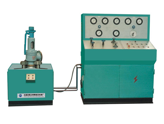
JLA safe valve test bench
Message If you want any further detail data and drawing,please contact us.
1, Overview
JLA safe valve test bench is my company's scientific and technical personnel on the basic of accordance with national GB/T1 3927-92 and ZBJl6006-90 standard reference to the advantages of similar foreign products, and combined with our many years of technical experience in producing valve testing equipment based on the successful development of its own China's first JLA-type safety valve performance testing.
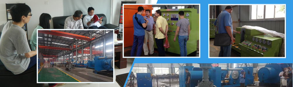
The machine has used in Maoming Petrochemical, Zhenhai Refinery Plant and other plants, praised by experts and certainty. The test bed eliminates channeling the original volume of conventional large high-pressure gas cylinders animals, just with the ordinary 0.6MPa Air pump gas source. Applies to the nominal diameter DN1 5 ~ 300 safety valve setting, open and close, back seat pressure
Strength and sealing actions such as performance testing. Has a stable performance, easy to use, high degree of automation test data correctly and so on.
Note: YFC-A (common type) safety valve performance testing machine for the pressure gas source pressure range the user-owned, and in the light of the explanatory information to use, does not provide for another manual, please understand.
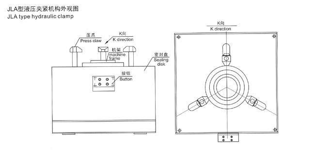
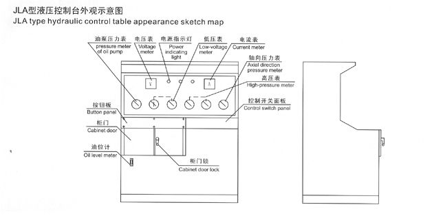
2, Working principle and structure
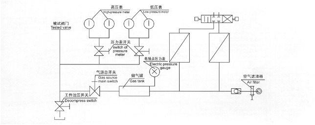
JLA safe valve test bench set machines, electricity, liquid in one, gas for the test medium, pressurized gas-liquid interaction, step-up device with a multi-polar system, functions to meet the required test pressure. Work piece clamping were tested by the valve flange face for positioning, hydraulic cylinder clamping flange clamps for clamping the back way. Test valve being no additional external influences, and in full compliance with the relevant national standards require that the valve inspection test requirements.
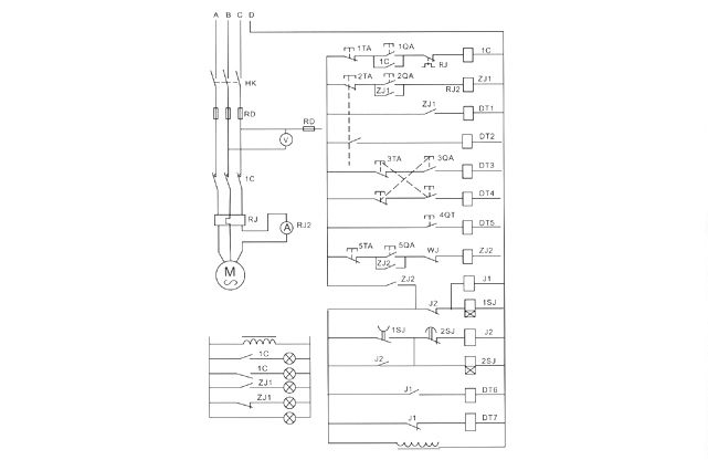
The aircraft hydraulic systems, mechanical components, electrical control and a multi-polar air supply booster system, etc. parts. Hydraulic system test bed is the main source of power. For all kinds of hydraulic cylinders and mechanical parts, it was driven executive function. Test surface clamps the implementation of direct-drive hydraulic cylinder, axial clamping pressure is based on a different level of the test pressure valve to adjust boost (maximum hydraulic pressure booster 31 5MPa). The clamps are all affected by forces, clamping and reliable. Radial movement by the hydraulic cylinder drive the implementation of advance and retreat of all clamps are synchronized, agile and free to ensure that the valve diameter size of the different tests. A multi-polar gas supply step-up device is the use of pressurized liquid-gas interaction. Booster range is 0.6-32 0MPa, medium pressure test for valves. Boost gas source with the work of two kinds of automatic and manual operation of choice, was elected with an automatic step-up work, staff can observe at close range to leave the console field test situation.
The test-bed gas source in the step-up the use of safety valve by the pressurized gas source to control the boost, electric contact pressure gauge designated stop.
3, Caution and safety requirements
1, equipment installation, the hydraulic control system and the table should be a certain distance, separated by location can not be less than 500mm, a good installation of the school level, with concrete bolts fixed at the end of feet.
2, with 30-40 # hydraulic oil into the fuel tank, fuel can not be less than the lower limit of the oil level gauge.
3, connect the power, by pump start button, check the direction of motor rotation is correct (clockwise direction), oil pump pressure regulator in 5.0MPa, to test machine, to check pipe joints is no leakage, and other noise, and found that undesirable phenomenon should be immediately overhauled.
4, test valve, the first valves were tested in accordance with test requirements; refer to "comparison table clamping cylinder pressure required to" carry out the necessary boost pressure regulation. Non-pressurized high
Work to prevent deformation of the valve damage was tested.
5, gas supply step-up work before the first electric contact pressure gauge pointer adjustment valves were tested in the test pressure required for the position, the high-voltage test light "liquid-gas linkage regulator control
Form "and then proceed to step-up work to achieve the required pressure to the specified requirements, pumps automatically stop working.
6, air filter used to work every day to check emissions, pipeline gas tank on the excretion of sub-L, a week on a regular basis check emissions.
7, test bench, and were tested valve sealing plate contact surfaces to maintain clean dry; dispute over oil and other debris are not allowed, this machine is strictly prohibited the use of work process depends Close.
8, hydraulic oil should be replaced periodically check for new oil injected into the use of about 5-6 months, oil filter and fuel tanks should be cleaned, and replaced with new oil, oil fuel tank temperature can not be super -
Than 60℃.
9, prohibited the use of illegal overpressure operation.

| Failure phenomenon | Causalion | Elimination method |
| The running parts of the cylinder creeps |
Air enters the trydraulic system | Loose the joint of the cylinder lo dxhaust and eliminate the possibily that the air enters the system,for instance, oil-skin,oil fiter,joint,valve and the aintinght packing. |
| The pressure couldn't be sel up to the medium while test the pressure of the pressurb of the valve lbad |
1、Pressure testing pumping source which provded by user fails The O typed ring was seriously scraped or damaged A、The blockage of the pressure oil pipe of the master cylinder |
Repair Change the spring Change the Otyped ring Process the fumow again Choose the suitable Clean the pipeline Choose another model |
| The dwell feature of the master cylinder reduces | ||
| Overflow valve The blockage of the pilot valve and primary valve core |
||
| The electromagnet is too hot or bums off |
The insulation of the wire coil is not good enough | Change the elecromagnet |
| The insulation of the wire coil is not adsorb steadily | Check the voltage and inon-core if thery are blockage or not |
|
| Wrong voltage | Comect the voltage | |
| The electrode does not weld steadily enough | Weld again | |
| Can't be boosted | The valve of boost control fails | Check and repair to eliminate |
| Seal loop is damaged | change the airtight packing | |
| The directional valve is not on-position | check and repair | |
| The dwell feature of the jam manometer reduces |
Oil-out valve is locked | clean the clear valve |
| Pilot-controlled valve core is locked | clean and repair;change | |
| The seal loop of the cylinder is damaged too much | check or changethe seal loo | |
| The directional valve can't reverse gear |
Electromanget is damages or not strong enough | Change electromanget |
| Port valve galls or lovks | Cean or repair the port valve | |
| There overruns a spring strength of crossover position valve | ||
| Electromanget suction or spring broken | Change the spring | |
| The frictional force of port valve is too large | Check the port valve joint and the two-port seal force |
|
model |
Specifications and Data |
the axlel pressure cylinder | radlal drlving and reveralng cylinder | Pressurized oil rainbow | |||||||||||
| Type YX | Type O | Type YX | Type O | Type YX | Type O | ||||||||||
| Seal loop |
Seal loop |
Seal loop |
Seal loop |
Seal loop |
Seal loop |
Seal loop |
Seal loop |
Seal loop |
Seal loop |
Seal loop |
Seal loop |
Seal loop |
Seal loop |
||
| D | d | Φ | Φ | Φ | D | d | J | Φ | Φ | D | D | Φ | Φ | ||
| YFC-A/100 | Specifications | 80 | 50 | 80 | 55 | 35 | 40 | 20 | 20 | 40 | 16 | 125 | 40 | 30 | |
| Data | 6 | 3 | 6 | 3 | 6 | 2 | 1 | 1 | 2 | 2 | 1 | 1 | 1 | ||
| YFC-A/200 | Specifications | 100 | 60 | 100 | 65 | 45 | 50 | 30 | 30 | 50 | 20 | 125 | 40 | 30 | |
| Data | 6 | 3 | 6 | 3 | 6 | 2 | 1 | 1 | 2 | 4 | 1 | 1 | 1 | ||
| YFC-A/300 | Specifications | 140 | 70 | 140 | 75 | 60 | 50 | 30 | 30 | 50 | 20 | 125 | 40 | 30 | |
| Data | 6 | 3 | 6 | 3 | 6 | 2 | 1 | 1 | 2 | 4 | 1 | 1 | 1 | ||
| 200 type clamping cylinder pressure contrast table | ||||||||||
| Nominal diameter DN |
Nominal pressure of valve MPa/class | |||||||||
| 1.6 | 2.5 | 4.0 | 6.4 | 10.0 | 16.0 | 20.0 | 25.0 | 32.0 | ||
| 150 | 300 | 400 | 600 | 900 | 1500 | |||||
| Hydraullc system pressure (Pressure increasing) | ||||||||||
| in | mm | pn | pn | pn | pn | pn | pn | pn | pn | pn |
| 2 | 50 | 3.0 | 3.0 | 3.0 | 3.0 | 3.0 | 4.0 | 6.0 | 7.0 | 9.0 |
| 2 | 65 | 3.0 | 3.0 | 3.0 | 3.0 | 4.0 | 6.0 | 8.0 | 9.0 | 12.0 |
| 3 | 80 | 3.0 | 3.0 | 3.0 | 4.0 | 6.0 | 9.0 | 12.0 | 15.0 | 18.0 |
| 4 | 100 | 3.0 | 3.0 | 4.0 | 60 | 9.0 | 14.0 | 17.0 | ||
| 6 | 15.0 | 4.0 | 5.0 | 7.0 | 11.0 | 17.0 | ||||
| 8 | 200 | 5.0 | 7.0 | 11.0 | 18.0 | |||||
| 100 type clamping cylinder pressure contrast table | |||||||||||
| Nominal diameter DN |
Nominal pressure of valve MPa/class | ||||||||||
| 1.6 | 2.5 | 4.0 | 6.4 | 10.0 | 16.0 | 20.0 | 25.0 | 32.0 | |||
| 150 | 300 | 400 | 600 | 900 | 1500 | ||||||
| Hydraullc system pressure (Pressure increasing) | |||||||||||
| in | mm | pn | pn | pn | pn | pn | pn | pn | pn | pn | |
| 1/2 | 15 | 3.0 | 3.0 | 3.0 | 3.0 | 3.0 | 3.0 | 3.0 | 3.0 | 4.0 | |
| 3/4 | 20 | 3.0 | 3.0 | 3.0 | 3.0 | 3.0 | 3.0 | 3.0 | 3.0 | 4.0 | |
| 1 | 25 | 3.0 | 3.0 | 3.0 | 3.0 | 3.0 | 3.0 | 4.0 | 5.0 | 6.0 | |
| 4(1/4) | 32 | 3.0 | 3.0 | 3.0 | 3.0 | 3.0 | 4.0 | 6.0 | 7.0 | 9.0 | |
| 1(2/1) | 40 | 3.0 | 3.0 | 3.0 | 3.0 | 4.0 | 6.0 | 7.0 | 9.0 | 11.0 | |
| 2 0 | 50 | 3.0 | 3.0 | 3.0 | 4.0 | 5.0 | 7.5 | 9.5 | 12.0 | ||
| 2 | 65 | 3.0 | 3.0 | 3.0 | 4.0 | 6.0 | 10.0 | 12.0 | |||
| 3 | 80 | 3.0 | 3.0 | 4.0 | 6.0 | 10.0 | 15.0 | ||||
| 4 | 100 | 3.0 | 4.0 | 6.0 | 9.0 | 14.0 | |||||