


- Valve testing equipment
- Pump-valve
- Gate valve
- Globe valve
- Check valve
- Butterfly valve
- Pump
- Ball valve
- Valve fittings
- Pneumatic Actuator
- Electric Actuator


 Zhejiang Youji Machinery Technology Co.,Ltd >> Product >> Valve testing equipment >> JLM valve hydraulic grinding machine
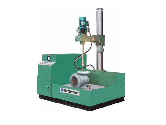
JLM valve hydraulic grinding machine
Message If you want any further detail data and drawing,please contact us.
1, Overview
With the rapid development of machine-building industry, hydraulic technology has been in the general machine tools and other equipment is widely applied, the company relies on technology to accumulate many years of manufacturing hydraulic drive
Equipment installation experience and has successfully developed advanced level of JLM hydraulic valve grinding machine. The machine has an advanced variable speed grinding disc rotation, mechanical eccentric
Public switched from turn-style to the principle of auto-lifting machine equipped with hydraulic jib, work piece clamping and automatic regulating valve angle of arbitrary functions. With easy to operate, fully functional, structural Ling
Coincidentally, advanced technology and high degree of automation of this function to complete the valve seat, valve flap sealing ring plane grinding. Accuracy of up to: 1.6 fine roughness of the sealing surface (hardness HRC36.50), diameter 15-30Min rhyme O 4 finishing up the degree of matching over 80%.
Proved through practice, not only the technical requirements for grinding a variety of valves are up to standard, but will also greatly improve efficiency and reduce labor intensity and well received by the valve manufacture, maintenance and so on petrochemicals industries welcome and praise.
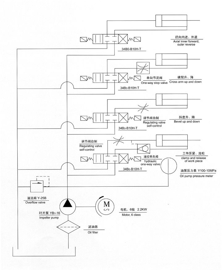
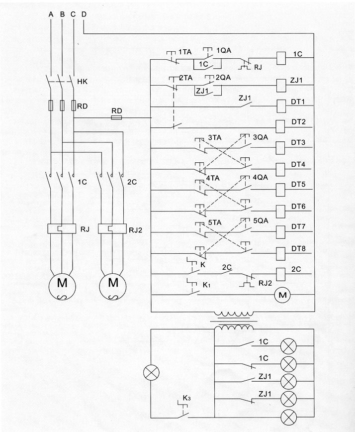
2, Working principle and structure
JLM-type grinding machine structure is broadly divided into the hydraulic system, mechanical systems and electrical control system has three major components. The hydraulic pump hydraulic system the pressure input ministries to carry out height, stroke and angle of the work and control. Arm movements by the implementation of hydraulic cylinder, in the middle can be either a high degree of choice. Work table equipped with two automatic clamping devices, by the hydraulic cylinder direct-drive to achieve, so that two clamps force uniform, clamping reliable, clip claws to move through the use of leverage, with compact structure, stable characteristics. Pros and cons of two pots can be used for grinding surfaces only. There is oil in the composition of the front stones used for dry finishing; the opposite may be sticky
Paste adhesive emery cloth coarse emery cloth or ordinary grinding process, (emery cloth by the user on their own purchase). When finishing, grinding methods used to conduct public switched eccentric turn, grinding with automatic return to cooling fluid lubricating oil, ground forces equipped with automatic retractable flexible regulatory function to maintain the work center of the correct location. The use of emery cloth grinding is not required to cool the oil.
3, Operation and notes
(1), the whole school level and at the end of the fixed machine foot screw installation.
(2), with 30 # -40 # 20 # hydraulic oil or machine oil in the hydraulic system oil tank, fuel can not be less than the oil level gauge in the limit.
(3), the preparation of grinding coolant Run by adding lubricating fluid tanks (preparation method see random data).
(4), boot check: Access to power, close the air switch, open the electric lock (pump stops and the indicator light), press (pump start), check the motor direction is correct (clockwise rotation
Rpm), and an empty load running a few minutes, adjust relief valve hand wheel, the oil pump pressure regulator to 5.0MPa, to check whether the leakage of joints (excluding leakage), the fuel tank can be a normal movement
Operation.
(5), [1]. The initial use, will be grinding the valve on the work of the table, to be grinding the sealing surface and the lapping tool and lapping over the entire center axis, and then grinding the workpiece is pressed, first
Jog (pressure claw forward), press (pressure claw clamp) button, to conduct research with boot rotate, adjust research with the best speed. For grinding.
[2]. According to the different valves, was to study the sealing surface is flat the entire school board scale to zero. Button, (adjusted slope l and adjusting the gradient descending), study of the seat and the valve gate valve angle of the bench
Valve regulated to the same degree angles, press (button to tune slope l), and then sealing surface, lapping tool and grinding axes over the entire center, clamp the workpiece, and research carried out with the boot rotating grinding (coarse Research
Or Lapping).
[3]. If the need to adjust the grind by grinding shaft 21 (see diagram) in the amount of swing eccentric, release the top tight screws, rotating inside the eccentric shaft, eccentric volume available to the different rotation, so that research
And the sealing surface with moving center of rotation changes, to improve the accuracy of the sealing surface.
(6), grinding process:
[1]. rough study is to eliminate the sealing surface of the abrasion, indentation, point defects such as corrosion, improve smoothness and lower sealing surface roughness degree of precision, in order to lay the base depth research study, using coarse
Grain emery cloth (paper) size of 80 # 1 280 #.
[2]. After inquiry by the sealing surface rough surface texture and deep but needs depth research, carried out by using smaller refinements of Hone, effectively improve the precision of the sealing surface can reach the final technical requirements.
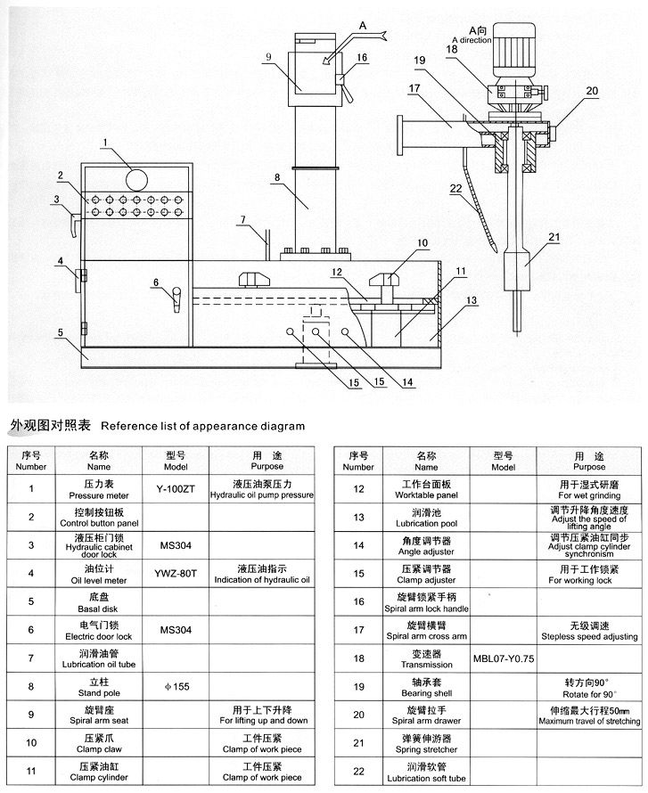
Reference list of appearance diagram
| Number | Name | Model | Purpose |
| 1 | Pressure meter | Y-100ZT | Hydraulic oil pump pressure |
| 2 | Control button panel | ||
| 3 | Hydraulic cabinet | MS304 | |
| 4 | Oil level meter | YWZ-80T | Indication of hydraulic oil |
| 5 | Basal disk | ||
| 6 | Electiric door lock | MS304 | |
| 7 | Lubrication oil tube | ||
| 8 | Stand pole | ф155 | |
| 9 | Spiral arm seat | For lifting up and down | |
| 10 | Clamp claw | Clamp of work plece | |
| 11 | Clamp cylinder | Clamp of work plece | |
| 12 | Worktable panel | For wet grinding | |
| 13 | Lubrication pool | Adjust the speed of lifting angle | |
| 14 | Angle adjuster | Adjust ctamp cylinder synchronism | |
| 15 | Clamp adjuster | For working lock | |
| 16 | Spiral arm lock handle | ||
| 17 | Spiral arm cross arm | Stepless speed adjusting | |
| 18 | Transmission | MBL07-Y0.75 | |
| 19 | Bearing shell | Rotate for 90° | |
| 20 | Spiral arm drawer | Maximum travel of stretching | |
| 21 | Spring stretcher | ||
| 22 | Lubrication soft tube |
| Failure phencmencn | Causation | Elimination method |
| The normal pressure can’t establish in hydraulic system |
1.Oil pump |
Change the wire of the oil pump and electrical Repair or change Screw down the connection or change the pipeline |
| 2.Overflow valve ① The blockage of the pilot valve and primary valve core. ② Orifice blockage ③ The spring of pnmary valve were distorted or broken |
Repair the valve core |
|
| 3.Pilot-controlled solenoid valve core was locked at the connection | Repair the valve core | |
| 4.Serious leakage of the cylinder and high-low pressure reach-through | Change the airtight packing and boring if the cylinder was tom too much | |
| 5.Manometer failure or the biockage of switch of the manometer and can’t reflect the true pressure of the system | Rub the hole of the cylinder and clean and change the piston | |
| Vibration with the noise | 1.The biockage of oil pipe or oil filter of the fuel tank so that the oil can’t go through well | Clean timing |
| 2.The oil is lack in the oil pipe | Add according to the oil level line | |
| 3.The blockage of the air cleaner on the faceplate of fuel tank | Clean | |
| 4.The large oil viscosity number increase the flowing force | Change the oil | |
| 5.The oil pump and the axle of the electrical machinery are not in concentricity | Adjust again until the non-concentricity is less than 0.1 | |
| 6.Vibration of the overflow valve and caused the system resonance | Check the elements of the valve and eliminate the causation of the resonance | |
| 7.The pipeline is too long and not rigid fixing | Change the pipe or repair | |
| 8.The damage of the fixing intemals | Change or repair |
| Part | Name | Specification | Quantity | Used for |
| Clamp cylinder | YX type sealing lcop for hole | D80 | 4 | Pistcn |
| YX type sealing loop for axis | D40 | 2 | Cover of cylinder | |
| O shaped ring | φ45×3.1 | 2 | Cover of cylinder | |
| O shaped ring | φ80×3.1 | 2 | Cover of cylinder | |
| O shaped ring | φ30×3.1 | 2 | Piston rod | |
| Spiral arm lifting cylinder | YX type sealing loop for hole | D50 | 2 | Piston |
| YX type sealing loop for axis | D30 | 1 | Cover of cylinder | |
| Dust collar | D30 | 1 | Cover of cylinder | |
| O shaped ring | φ50×3.1 | 1 | Cover of cylinder | |
| O shaped ring | φ20×2.4 | 1 | Piston rod | |
| Inner oil feeding outer back cylinder | YX type sealing loop for hole | D50 | 2 | Piston |
| YX type sealing loop for axis | D30 | 1 | Cover of cylinder | |
| Dust collar | D30 | 1 | Cover of cylinder | |
| O shaped ring | φ50×3.1 | 1 | Cover of cylinder | |
| O shaped ring | φ20×2.4 | 1 | Piston rod | |
| Angle lifting cylinder | YX type sealing loop for hole | D80 | 2 | Piston |
| YX type sealing loop for axis | D30 | 1 | Cover of cylinder | |
| Dust collar | D30 | 1 | Cover of cylinder | |
| O shaped ring | φ80×3.1 | 1 | Cover of cylinder | |
| O shaped ring | φ20×2.4 | 1 | Cover of cylinder | |
| For tubes | O shaped ring | φ18×2.4 | 10 | Piston rod |
| O shaped ring | φ10×1.9 | 20 | Oil tube |