


- Valve testing equipment
- Pump-valve
- Gate valve
- Globe valve
- Check valve
- Butterfly valve
- Pump
- Ball valve
- Valve fittings
- Pneumatic Actuator
- Electric Actuator


 Zhejiang Youji Machinery Technology Co.,Ltd >> Product >> Valve testing equipment >> JWT welding valve hydraulic test bench
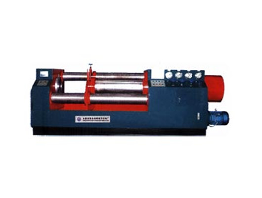
JWT welding valve hydraulic test bench
Message If you want any further detail data and drawing,please contact us.
1, Overview
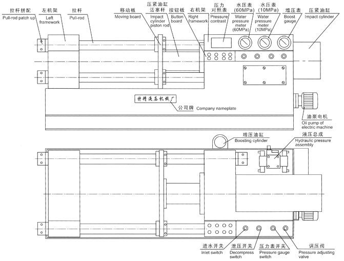
JWT welding valve hydraulic test bed is on the basic of my company's production of valves for many years of experience on the basis of testing equipment, to address the valve manufacturer, valve can not be right to use other units such as valves and blue style <J61,J63,Z61> Flanged valves of different types can be a testing machine for testing the requirements of the "universal valve pressure test" and "valve testing and detection" of the standard specification requirements, design. Making top-pressure type valve testing equipment, the machine set of hydraulic, electromechanical, test pressure and liquid medium used for storage of cycle one, with a reasonable structure, perfect function and convenient operation etc., are widely used in nominal diameter DNl5-800mm all kinds of high intensity and low-pressure valve seal . Good performance tests, the maximum seal test pressure 32.0MPa, strength tests 48.0MPa.
2, Working principle and Structure
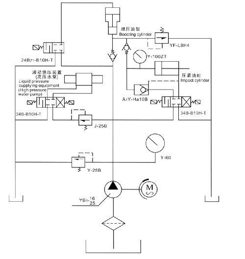
JWT hydraulic valve test bench set welded hydraulic, mechanical, electrical, hydraulic pump in one for the use of hydraulic clamping. Pairs of valves were tested for performance tests. Hydraulic system test bed is the main source of power for the hydraulic fluid for the pump-driven and functional performance. Hydraulic clamping cylinder working pressure is based on a different level of the test pressure valve to adjust boost (maximum hydraulic boost pressure 31.5MPa). Hydraulic pump installations for micro-pressure and high pressure 2 files, in accordance with this test sequence of operations, in the electrical and vacuum regulator valve under the control of media to pressure test the valve for the water pump pressure range 0.4-48.0MPa, for the pressure medium anti-rust water or oil. The test bed is set at the bottom of the storage tanks to ensure the recycling of liquid medium.
3, Notes and requirements
(1), equipment installation: the school a good level of equipment, placement, or a fixed foot concrete bolts.
(2), use 30 - 40 # 20 # hydraulic oil or machine oil into the fuel tank, fuel can not be less than the lower limit of the oil level gauge.
(3), to ensure that subjects were no corrosion and the native valve for pressure medium demands and needs. Local storage tanks of liquid medium for anti-rust water or oil, according to usage conditions into the storage tanks.
(4), connected to power, according to pump starting, check the motor rotation direction is correct (clockwise direction) to regulate the pump pressure in the 5 0MPa test-machine, to check whether the leaking pipe and found that negative phenomena should be immediately overhauled.
(5), test valve, the first valves were tested according to test requirements refer to "compress cylinder pressure required to control the table" to test pressure booster regulator. Non-pressurized high pressure job, Prevent damage to test the valve deformation.
(6), hydraulic pump for the job before the first vacuum regulating valve located in the appropriate use of pressure adjustment position, and then medium pressure of work.
(7), water storage tank of liquid test medium, to be changed regularly to the newly launched anti-rust water or oil in a month or so the use of storage tanks should be cleaned at the same time replacement of anti-rust water, after three months or six cycles. 8, fuel tank and oil filters should be periodically cleaned, oil tank regularly to replace oil temperature should not exceed 55 ~ C.
(8), test bench rod surface and the activities of Department, should regularly refuel and maintain the use of lubrication.
4, Appearance diagram
5, Use method
(1), subjects were valve setup:
Were tested according to the size of the valve diameter, were tested first, to readjust the valve positioned frame and the point of commencement pieces of pressed button, will move into the baffle into the pressure test valves were tested next to the appropriate location, and then were tested valves placed in the position shelf, then move the work piece clamping.
(2), pressed pressurization:
Valves were tested according to the nominal diameter and nominal pressure to regulate the electric contact pressure gauge and the valves were tested the same. Reference to "clamping cylinder pressure required to control the table" will be pressed to the desired tank pressure to boost pressure. (Note: The booster button to move will happen in many points, each time interval between pressing need in the 5-10 seconds or so).
(3), liquid medium pressure:
The test pressure valves were tested according to requirements, the first reference to "pressure from hydraulic pressure for the comparison table" will be transferred decompression valve located in the work required for the pressure position. Open the water valve switch. (Check the intake valve switch is closed) first started low-pressure water pump and achieve low-voltage requirements, and then pump start button to carry out hydraulic pressure to the required pressure for automatic stop IE.
(4), testing is completed Pressure Relief:
Valve testing is complete, turn off water valve switch to open the pressure relief valve switch, the pressure medium pressure discharge is finished, the work of relaxed jog button, remove the valves were tested. In accordance with the above procedures and then test the other valve.
(5,) air dielectric test:
Access to the gas source inlet, turn off water valve switch on the road to open the inlet valve switch in preparation for operational requirements, performance tests can be carried out air medium.
JWT/100 type clamping cylinder pressure contrast table
| Nominal diameter DN |
Nominal pressure of valve MPa/class | ||||||||||||||||
| 2.5 | 4.0 | 6.4 | 10.0 | 16.0 | 20.0 | 25.0 | 32.0 | ||||||||||
| 150 | 300 | 400 | 600 | 900 | 1500 | ||||||||||||
| Hydraulic system pressure (Pressure increasing) | |||||||||||||||||
| in | mm | PN | PS | PN | PS | PN | PS | PN | PS | PN | PS | PN | PS | PN | PS | PN | PS |
| 3/4 | 20 | 3.0 | 3.0 | 3.0 | 3.0 | 3.0 | 3.0 | 4.0 | 4.0 | 4.0 | 4.0 | 4.0 | 6.0 | 6.0 | 6.0 | 6.0 | 6.0 |
| 1 | 25 | 3.0 | 3.0 | 3.0 | 3.0 | 3.0 | 3.0 | 4.0 | 4.0 | 4.0 | 4.0 | 4.0 | 6.0 | 6.0 | 6.0 | 6.0 | 6.0 |
| 11/4 | 32 | 3.0 | 3.0 | 3.0 | 3.0 | 3.0 | 3.0 | 4.0 | 4.0 | 6.0 | 6.0 | 6.0 | 6.0 | 6.0 | 6.0 | 6.0 | 6.0 |
| 11/2 | 40 | 3.0 | 3.0 | 3.0 | 3.0 | 4.0 | 4.0 | 4.0 | 4.0 | 6.0 | 6.0 | 6.0 | 6.0 | 6.0 | 6.0 | 6.0 | 8.0 |
| 2 | 50 | 3.0 | 3.0 | 3.0 | 3.0 | 4.0 | 4.0 | 4.0 | 4.0 | 6.0 | 6.0 | 6.0 | 6.0 | 6.0 | 8.0 | 7.0 | 10.5 |
| 21/2 | 65 | 3.0 | 3.0 | 3.0 | 3.0 | 4.0 | 4.0 | 4.0 | 6.0 | 6.0 | 9.0 | 7.0 | 10.5 | 9.0 | 13.5 | 12.0 | 18.0 |
| 3 | 80 | 3.0 | 3.0 | 3.0 | 3.0 | 4.0 | 4.0 | 5.0 | 7.5 | 7.0 | 10.5 | 8.0 | 12.5 | 11.0 | 16.0 | 15.0 | 22.5 |
| 4 | 100 | 3.0 | 3.0 | 3.0 | 3.0 | 4.0 | 6.0 | 6.0 | 9.0 | 10.0 | 15.0 | 13.0 | 19.5 | 17.0 | 25.5 | 20.0 | 30.0 |
JWT/200 type clamping cylinder pressure contrast table
| Nominal diameter DN |
Nominal pressure of valve MPa/class | ||||||||||||||||
| 2.5 | 4.0 | 6.4 | 10.0 | 16.0 | 20.0 | 25.0 | 32.0 | ||||||||||
| 150 | 300 | 400 | 600 | 900 | 1500 | ||||||||||||
| Hydraulic system pressure (Pressure increasing) | |||||||||||||||||
| in | mm | PN | PS | PN | PS | PN | PS | PN | PS | PN | PS | PN | PS | PN | PS | PN | PS |
| 2 | 50 | 3.0 | 3.0 | 3.0 | 3.0 | 3.0 | 3.0 | 3.0 | 3.0 | 3.0 | 3.0 | 3.0 | 4.0 | 3.0 | 4.0 | 3.0 | 5.0 |
| 21/2 | 35 | 3.0 | 3.0 | 3.0 | 3.0 | 3.0 | 3.0 | 3.0 | 3.0 | 3.0 | 4.0 | 3.0 | 4.5 | 4.0 | 6.0 | 4.0 | 6.0 |
| 3 | 80 | 3.0 | 3.0 | 3.0 | 3.0 | 3.0 | 4.0 | 3.0 | 3.0 | 3.0 | 4.5 | 4.0 | 6.0 | 4.0 | 7.0 | 5.0 | 7.5 |
| 4 | 100 | 3.0 | 3.0 | 3.0 | 3.0 | 3.0 | 5.0 | 3.0 | 4.0 | 4.0 | 6.0 | 4.5 | 7.0 | 5.0 | 7.5 | 5.5 | 8.5 |
| 6 | 150 | 4.0 | 4.0 | 4.0 | 4.0 | 4.0 | 4.0 | 4.0 | 5.0 | 5.0 | 7.5 | 6.5 | 10.0 | 8.0 | 12.0 | 11.0 | 16.5 |
| 8 | 200 | 4.0 | 4.0 | 4.0 | 4.0 | 4.0 | 5.5 | 5.5 | 8.0 | 8.5 | 13.0 | 10.0 | 15.0 | 13.0 | 20.0 | 17.0 | 25.5 |
JWT/300 type clamping cylinder pressure contrast table
| Nominal diameter DN |
Nominal pressure of valve MPa/class | ||||||||||||||||
| 2.5 | 4.0 | 6.4 | 10.0 | 16.0 | 20.0 | 25.0 | 32.0 | ||||||||||
| 150 | 300 | 400 | 600 | 900 | 1500 | ||||||||||||
| Hydraulic system pressure (Pressure increasing) | |||||||||||||||||
| in | mm | PN | PS | PN | PS | PN | PS | PN | PS | PN | PS | PN | PS | PN | PS | PN | PS |
| 3 | 80 | 3.0 | 3.0 | 3.0 | 3.0 | 3.0 | 3.0 | 3.0 | 3.0 | 3.0 | 3.5 | 3.0 | 4.0 | 3.0 | 4.5 | 3.5 | 5.5 |
| 4 | 100 | 3.0 | 3.0 | 3.0 | 3.0 | 3.0 | 3.0 | 3.0 | 3.0 | 3.0 | 4.0 | 3.0 | 4.5 | 4.0 | 6.0 | 5.0 | 7.5 |
| 5 | 125 | 3.0 | 3.0 | 3.0 | 3.0 | 3.0 | 3.0 | 3.0 | 3.0 | 3.0 | 4.5 | 4.0 | 6.0 | 5.0 | 7.5 | 6.5 | 9.0 |
| 6 | 150 | 3.0 | 3.0 | 3.0 | 3.0 | 3.0 | 3.0 | 3.0 | 4.5 | 4.5 | 7.0 | 6.0 | 9.0 | 7.0 | 10.5 | 9.0 | 13.5 |
| 8 | 200 | 3.0 | 3.0 | 3.0 | 3.0 | 3.0 | 5.0 | 4.5 | 7.0 | 7.5 | 11.5 | 9.0 | 13.5 | 11.5 | 17.0 | 15.0 | 22.5 |
| 10 | 250 | 3.0 | 3.0 | 3.0 | 4.0 | 4.5 | 7.0 | 7.0 | 10.0 | 11.0 | 16.5 | 13.5 | 20.0 | 17.0 | 25.5 | ||
| 12 | 300 | 3.0 | 4.0 | 4.0 | 6.0 | 6.0 | 9.0 | 9.5 | 14.0 | 15.0 | 22.5 | 18.0 | 27.0 | 20.0 | 30.0 | ||
JWT/400 type clamping cylinder pressure contrast table
| Nominal diameter DN |
Nominal pressure of valve MPa/class | ||||||||||||||||
| 2.5 | 4.0 | 6.4 | 10.0 | 16.0 | 20.0 | 25.0 | 32.0 | ||||||||||
| 150 | 300 | 400 | 600 | 900 | 1500 | ||||||||||||
| Hydraulic system pressure (Pressure increasing) | |||||||||||||||||
| in | mm | PN | PS | PN | PS | PN | PS | PN | PS | PN | PS | PN | PS | PN | PS | PN | PS |
| 4 | 100 | 3.0 | 3.0 | 3.0 | 3.0 | 3.0 | 3.0 | 300 | 3.0 | 3.0 | 4.0 | 3.0 | 4.5 | 4.0 | 6.0 | 5.0 | 7.5 |
| 5 | 125 | 3.0 | 3.0 | 3.0 | 3.0 | 3.0 | 3.0 | 3.0 | 3.0 | 3.0 | 4.5 | 4.0 | 6.0 | 5.0 | 7.5 | 6.5 | 9.0 |
| 6 | 150 | 3.0 | 3.0 | 3.0 | 3.0 | 3.0 | 3.0 | 3.0 | 4.5 | 4.5 | 7.0 | 6.0 | 9.0 | 7.0 | 10.5 | 9.0 | 13.5 |
| 8 | 200 | 3.0 | 3.0 | 3.0 | 3.0 | 3.0 | 5.0 | 4.5 | 7.0 | 7.5 | 11.5 | 9.0 | 13.5 | 11.5 | 17.0 | 15.0 | 22.5 |
| 10 | 250 | 3.0 | 3.0 | 3.0 | 4.0 | 4.5 | 7.0 | 7.0 | 10.0 | 11.0 | 16.5 | 13.5 | 20.0 | 17.0 | 25.5 | ||
| 12 | 300 | 3.0 | 4.0 | 4.0 | 6.0 | 6.0 | 9.0 | 9.5 | 14.0 | 15.0 | 22.5 | 18.0 | 27.0 | 20.0 | 30.0 | ||
| 14 | 350 | 3.5 | 5.0 | 5.0 | 7.5 | 8.0 | 12.0 | 12.5 | 18.5 | 20.0 | 30.0 | ||||||
| 16 | 400 | 4.0 | 6.0 | 6.5 | 10.0 | 10.5 | 16.0 | 16.0 | 24.0 | ||||||||
JWT/500 type clamping cylinder pressure contrast table
| Nominal diameter DN |
Nominal pressure of valve MPa/class | ||||||||||||||||
| 2.5 | 4.0 | 6.4 | 10.0 | 16.0 | 20.0 | 25.0 | 32.0 | ||||||||||
| 150 | 300 | 400 | 600 | 900 | 1500 | ||||||||||||
| Hydraulic system pressure (Pressure increasing) | |||||||||||||||||
| in | mm | PN | PS | PN | PS | PN | PS | PN | PS | PN | PS | PN | PS | PN | PS | PN | PS |
| 8 | 200 | 3.0 | 3.0 | 3.0 | 3.0 | 3.0 | 5.0 | 4.5 | 7.0 | 7.5 | 11.5 | 9.0 | 13.5 | 11.5 | 17.0 | 15.0 | 22.5 |
| 10 | 250 | 3.0 | 3.0 | 3.0 | 4.0 | 4.5 | 7.0 | 7.0 | 10.0 | 11.0 | 16.5 | 13.5 | 20.0 | 17.0 | 25.5 | ||
| 12 | 300 | 3.0 | 4.0 | 4.0 | 6.0 | 6.0 | 9.0 | 9.5 | 14.0 | 15.0 | 22.5 | 18.0 | 27.0 | 20.0 | 30.0 | ||
| 14 | 350 | 3.5 | 5.0 | 5.0 | 7.5 | 8.0 | 12.0 | 12.5 | 18.5 | 20.0 | 30.0 | ||||||
| 16 | 400 | 4.0 | 6.0 | 6.5 | 9.7 | 10.5 | 16.0 | 16.0 | 24.0 | ||||||||
| 18 | 450 | 5.0 | 7.5 | 8.0 | 12.0 | 13.0 | 19.5 | 20.0 | 30.0 | ||||||||
| 20 | 500 | 6.0 | 9.0 | 10.0 | 15.0 | 16.0 | 24.0 | ||||||||||
JWT/600 type clamping cylinder pressure contrast table
| Nominal diameter DN |
Nominal pressure of valve MPa/class | ||||||||||||||
| 1.0 | 1.6 | 2.5 | 4.0 | 6.4 | 10.0 | 16.0 | |||||||||
| 150 | 300 | 400 | 600 | 900 | |||||||||||
| Hydraulic system pressure (Pressure increasing) | |||||||||||||||
| in | mm | PN | PS | PN | PS | PN | PS | PN | PS | PN | PS | PN | PS | PN | PS |
| 12 | 300 | 3.0 | 3.0 | 3.0 | 3.0 | 3.0 | 3.0 | 5.0 | 7.5 | 7.5 | 11.5 | 12.0 | 18.0 | 18.0 | 27.0 |
| 14 | 350 | 3.0 | 3.0 | 3.0 | 3.0 | 3.0 | 4.5 | 6.5 | 10.0 | 10.0 | 15.0 | 16.0 | 24.0 | ||
| 16 | 400 | 3.0 | 3.0 | 3.0 | 4.0 | 3.5 | 5.5 | 8.0 | 12.0 | 13.0 | 19.5 | 19.0 | 28.5 | ||
| 18 | 450 | 3.0 | 3.0 | 3.0 | 4.0 | 5.0 | 7.5 | 10.0 | 15.0 | 16.0 | 24.0 | ||||
| 20 | 500 | 3.0 | 3.0 | 3.5 | 5.0 | 5.5 | 8.5 | 12.0 | 18.0 | 18.0 | 27.0 | ||||
| 24 | 600 | 3.0 | 4.5 | 5.0 | 7.5 | 8.0 | 12.0 | 13.0 | 20.0 | 20.0 | 30.0 | ||||
JWT/800 type clamping cylinder pressure contrast table
| Nominal diameter DN |
Nominal pressure of valve MPa/class | ||||||||||||||
| 1.0 | 1.6 | 2.5 | 4.0 | 6.4 | 10.0 | ||||||||||
| 150 | 300 | 400 | 600 | ||||||||||||
| Hydraulic system pressure (Pressure increasing) | |||||||||||||||
| in | mm | PN | PS | PN | PS | PN | PS | PN | PS | PN | PS | PN | PS | ||
| 16 | 400 | 3.0 | 3.0 | 3.0 | 4.0 | 3.5 | 5.5 | 8.0 | 12.0 | 13.0 | 19.5 | 19.0 | 28.5 | ||
| 18 | 450 | 3.0 | 3.0 | 3.0 | 4.0 | 5.0 | 7.5 | 10.0 | 15.0 | 16.0 | 24.0 | ||||
| 20 | 500 | 3.0 | 3.0 | 3.5 | 5.0 | 5.5 | 8.5 | 12.0 | 18.0 | 18.0 | 27.0 | ||||
| 24 | 600 | 3.0 | 4.5 | 5.0 | 7.5 | 8.0 | 12.0 | 13.0 | 20.0 | 20.0 | 30.0 | ||||
| 28 | 700 | 4.5 | 7.0 | 7.5 | 10.5 | 11.0 | 16.5 | 18.0 | 27.0 | ||||||
| 32 | 800 | 6.0 | 9.0 | 9.5 | 14.5 | 15.0 | 22.5 | 21.0 | 31.5 | ||||||