


 Zhejiang Youji Machinery Technology Co.,Ltd >> Product >> Valve fittings >> Electric Actuator >> aox
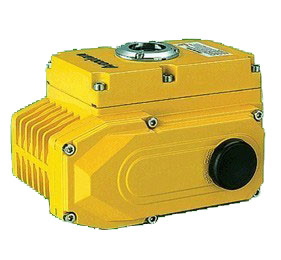
aox
Message If you want any further detail data and drawing,please contact us.
| Series : | Electric Actuator |
| Name : | aox |
| Model : | aox |
| PDF-DOWNLOAD : | |
| Click : | 313 |
|
Electric Machinery Manual Structure Indicator Desiccator Sealling Limit switch Self-locking Anti-off bolt Install Circuitry Performance Parameter
Standard Technical Parameter
Outside View
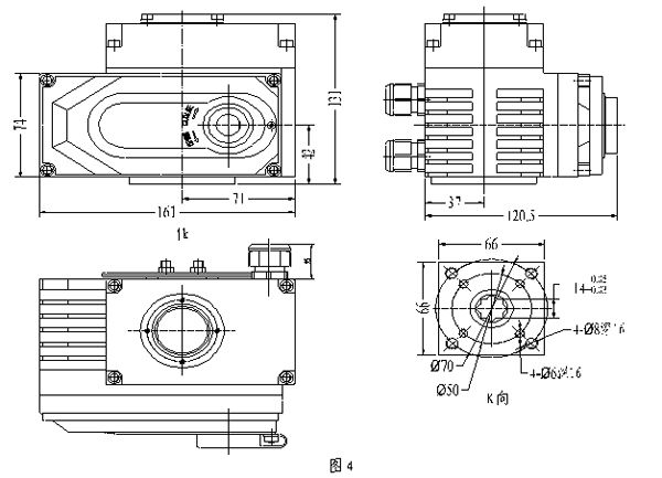
OMRX-05~08 Appearance and installation dimension
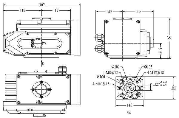
  OMRX-20~80/Appearance and installation dimension
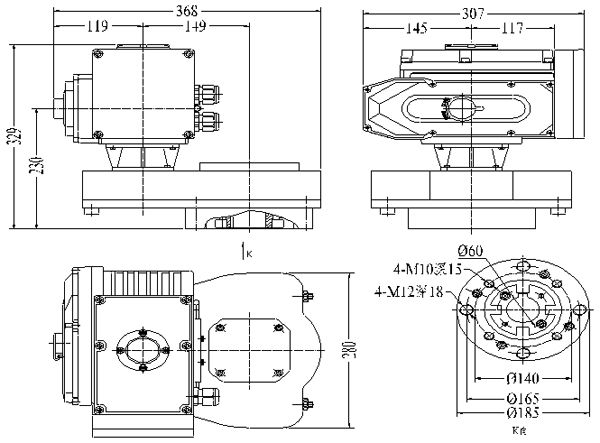
 OMRX100~300 Appearance and installation dimension
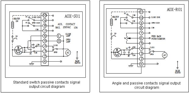
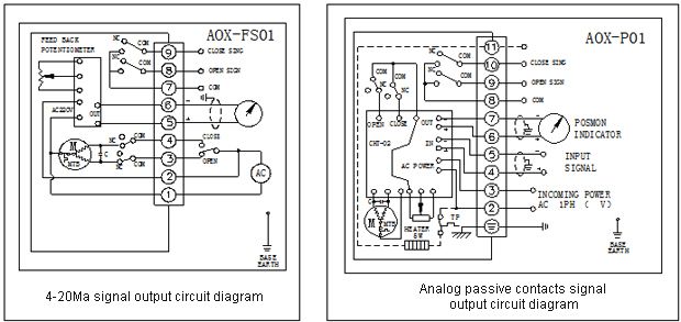
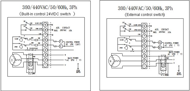
 Circuit Diagram
   Structure
Electric actuators is make up of the following parts
◎Shell: including shell and pedestal
◎drive parts:Whole sealing high-performance squirrel-cage motor for the power source
◎driving mechanism:Double worm gear and clutch parts
◎ratio control parts:separate with the mechanical parts, easy to debug
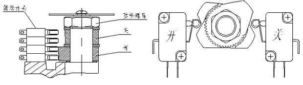
◎Limit switch Part
◎Opening Detected and Feedback Part
Installation of Electric actuators
Installation sites
Notes of interior installation
Ø It’s not a explosion-proof product, so that please don’t install in the place of explosive gases
Ø Add a protective cover when it installs in the water splashing place
Ø Please reserve space for repairing cables, manual operation.
Notes of outdoor installation
Ø In order to avoid the rain, direct sunlight and so on, it needs to install a protective cover.
Ø or choose IP68 protection grade
Ø Please reserve space for repairing cables, manual operation.
Ambient temperature and The condition of Fluid temperature
Ambient temperature
Ø Ambient temperature at 30℃~+60℃
Ø when Ambient temperature is below zero, the machine needs to install dehumidify desiccator.
The condition of Fluid temperature
Ø when using with the valve, the heat of the fluid will move to the body, then the body temperature will rise.
When the fluid temperature is a high temperature, the bracket which is connecting with the valve need to make special treatment.
Ø Standard bracket: fluid temperature below +65 ℃
Ø Intermediate temperate bracket:Fluid temperature over +65 ℃
Ø High-temperature bracket: Fluid temperature over +120 ℃
Connect with the valve
Turning valves by hand, confirmed that it didn’t have abnormal situation, then go to full-closed position;
Fix the bracket on the valve
Put the electric actuator on the bracket, then tweaking the screw bolts and nuts lightly
Put the electric actuator to the closed position, fixing valve mandrel and electric actuator with coupling and screw bolts
Screw the electric actuator and the bracket
Rotate the electric actuator by handle to confirm non-eccentric, curved ramps, balance exercises, and pay attention to don’t over travel
Note: Decrease hysteresis of the coupling as far as possible.
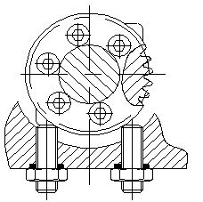
Pay attention to keeping the switch of electric actuator in line with the switch of the valve when installing. The flange of the electric actuator bottom accord with the standard ISO5211, if the valves connect with the flange is also conform to this standard,it will be connect conveniently; if doesn’t, it would connects with the bracket in addition.
Debug Description
stroke limit adjustments
Turn round handwheel,let the electric actuator move to the full-closed location. And loosen nuts on limit cam by spanner, rotating cam limit (yellow open, red off) to adjust to just push down limit switch (CLS) position, and then screw limit cam nut. So, it’s the way to set the full-closed limit position of the electric actuator. Wide-open position is setting as the same way.
 Mechanical limit adjustments
Loosen the nuts of the mechanical limit, and then move the electric actuator to the full-closed position by hand, rotating the limit nuts,stop rotating when it comes across inside the fan-shaped gear, and then circle out twice, screw the nuts at last. So, it’s the way to set the full-closed mechanical position of the electric actuator. Wide-open position is setting as the same way.As the following pictures:
 Running test
Manual Operation
First of all, it should be cut off the power,when it’s operating by hand; take off the rubber caps on the gear cover, put the accessory handle in the hexagonal hole; rotate the handle clockwise direction to reduce the opening.
Note: Opening to the wide-open or full closed position, limit switch turns half round, it will comes across mechanical block, if rotate excessively, it would result the damage of other parts, so it should be avoid excessive force.
Electric operation
1.Before electric operation, checking opening meters in line with the angle of valves by the methods of manual operation(wide-open, full-closed);
2.Check the wiring correct, at the same time need to use an external switch to confirm opening and closing movements;
3.After confirm the over status,then start electric operation
NOTE
check wiring diagram, power supply, input/output signal correctly.
Don’t change the internal wiring.
If the power supply is 3PH, it should be checking the rotating direction.
Enable the electric actuator lies in a half on / off position, turn on electricity and input the open signal.
If the electric actuator runs to the open position,it means the wiring is correct.
If the running direction is opposite, it must be change 2 pieces wiring in 3 pieces of wiring.
Maintenance
Oiling: Because of using the long life, good pressure resistance of Mo-based special grease, so it doesn’t need to add the oil
Regular operation: When the valve works infrequently, it should drive the machine regularly, checking abnormality or not.
Fault status & Countermeasure
|